Starting the Tuning Fork Gyroscope, Background
For my sensors class, we have been tasked with designing some form of a sensor from the ground up. My group, consisting of a grad student, a fellow undergrad and myself, chose to implement a gyroscope. Gyroscopes are instruments used for measuring angular rotation. They are commonly packaged with accelerometers and other sensors to form an IMU, an inertial measurement unit.
Theory of Operation
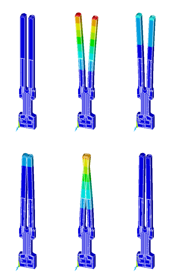
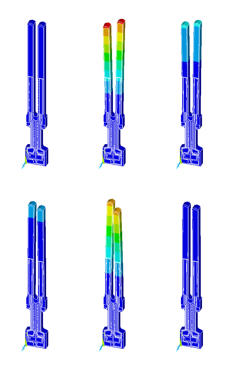
Some modern mems-based gyroscopes use a double ended tuning fork design for detecting rotation. The working principle of these sensors is fairly simple. Imagine a musical tuning fork, when struck on one of the tines, both will laterally oscillate side to side at the resonant frequency of the fork. However, if the fork was spun by its base the tines will experience a transverse force causing them to oscillate forward and backward. This amplitude is proportional to the rotational forces and thus angular velocity.
Detection
Following this phenomenon, we have decided to implement it with actual tuning forks. For our case, we won’t be able to measure the capacitive change as the forks move, so we require something a little more direct.
What quickly came to mind was, measuring the audio response with microphones or affixing strain gauges or piezoelectric transducers to the easy and hard axis of the fork. As a factor of noise, we chose against the audio method as the signal-to-noise ratio (SNRR) would be enormous and consequently the digital signal processing would not be feasible. That left a decision to be made between resistive strain gauges or piezoelectric transducers.

Measure circuit: Wheatstone bridge.
Observed due to a change in the electrical resistivity of a semiconductor or metal when mechanical strain is applied.
- Stable for static measurements. Essentially no drift.
- Perform very well for large loads.
- Very cheap.
- Highly resilient, high mechanical lifetime.
- Temperature sensitive.
- Self heating due to detection circuity.
- Limited sensitivity to small deviations.
- Limited sensitivity to high frequency deviations.

Measure circuit: Instrumentation or Charge Amplifier.
Operates on electric charge accumulation which occurs in certain solid materials (such as crystals) in response to applied mechanical stress.
- Great performance for small loads.
- Better for dynamic applications due to small deformation for induced forces, thus has a high resonance frequency range.
- Drift for static applications. Especially bad for small loads over long periods.
- Slightly more expensive.
See HBM for more information.
We wish to have the fastest detection rate of an angular velocity (fast impulse response) so it is best to have a faster resonant frequency tuning fork. This way there will be more sinusoidal cycles and thus valid ADC samples to detect the motion. Likewise, as we are detecting the tines moving merely by the Coriolis force, the deformations are not expected to be large. From these design requirements, a piezoelectric transducer is clearly the better choice in this application.
Driving
Now that it appears to be possible to detect the deformations, we need to find a way to get the fork to oscillate.
Intuitively, it makes sense to just wack a tine as one normally would with a tuning fork. This could be achieved with linear solenoid, think doorbell. However, this gives a dampening output. There would be an initial peak strike and as time goes on the amplitude of the tuning fork oscillations would decay. This would be problematic as we are attempting to detect the angular velocity as an amplitude measurement of the transverse force; which is proportional to the lateral forces at play when oscillating.
Thinking more about operating principles of a solenoid, a coil of wire and a magnet. Why not affix a magnet to a tine and drive with an electromagnet? We plan on affixing an equal sized magnet to each tine (as to keep the tuning fork in balance) and then driving with a bipolar electromagnet.
Getting Started
The next steps are to wait for our parts to arrive. Our BOM is as follows:
- 2x Piezoelectric strain gauges
- 1x 256 Hz Tuning fork
- 1x Electromagnet
- Assorted op-amps and components (for amplification, filtering, and driving)
- 3D printed stand


