Testing ER-TFTM028-4 Capacitve Touch Display
Good debugging equipment priceless. Being able to gain insight into a system in a quick and clear manner greatly helps identify when issues occur. In first versions I like to add visual feedback for myself. This can be as simple as an RGB LED to detect status or as full featured as a touch screen display.
For my senior design project we are designing an IOT home product that has many interconnected parts between the hardware and the base station. Being able to walk around with the device in hand will make it easier to calibrate and test. For this reason, I chose a cheap (~$17) capacitive TFT touch screen display, the ER-TFTM028-4 from BuyDisplay
As the senior design project is still in the design stage and the display shipment came in early, I wanted to do a few quick tests to verify device operation with the datasheet. This way, if I find any anomalies I have time to correct them or find a replacement part.
Power On
When testing a new device, my first step is to always apply power with a low current limit. This way I can determine if there are any disconnections or shorts. These issues would immediately present themselves as a constant current (CC) condition on the power supply. While normal operation would show the typical constant voltage (CV) as the device is not power starved.
In this case, I configured my RIGOL DP832 for 3.3V @ 10mA, then connected VCC and VSS. To my surprise, the supply immediately went into CC mode. Checking my connections and referencing the datasheet, I decided to check all the configuration jumpers on the back. Turns out the JP jumper for power was not connected. This is what bypasses the 5V->3.3 AMS1117 LDO U3. This still does not explain the CC condition. Then I decided to up the supply the currently configured 5V operation, the backlight dimly illuminated. Ah.
Fet Board Layout
Fet 3D Rendered Layout
I already made these images before I fully reversed engineered, and well it's a NPN BJT not really a FET. Oops. I'm not going to recreate as the idea still holds up.
Prebiased Transistor
Through a little reverse-engineering with my multimeter, I was able to create the following schematic:
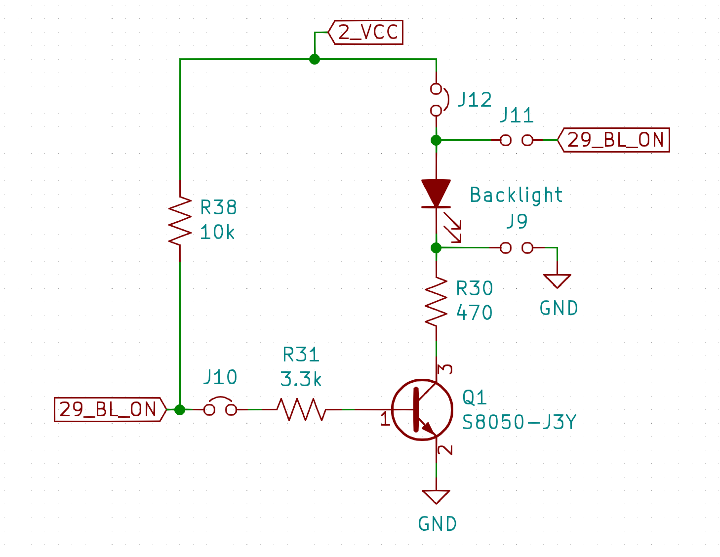
This explains why the display dimly lights when the drive pin is floating. The NPN transistor is already biased through the 10k and 3.3k in series, creating a base current of ~20uA corresponding to a collector current of ~2mA.
Personally I do not like this design, as there will always be a brief white flash of the backlight as the microcontroller is initializing its GPIOs. To get rid of this flash, it would be possible to pull the signal down harder with say a 1k to ground to overpower the 10k. But that would use up 3.3mA while the backlight is in operation and depending on the microcontroller may not be possible. Realistically, the best approach is probably de-solder R38, located right next to the SD card, and add a 100k pulldown on the end device. ...Or just let it go, I'll leave that up to you.
Determining VCC Voltage
| Input Voltage (V) | State | Current (A) | Power (W) |
|---|---|---|---|
| 5.0 | On | 0.10 | 0.501 |
| 3.3 | On | 0.10 | 0.330 |
| 5.0 | Float | 0.05 | 0.250 |
| 3.3 | Float | 0.05 | 0.165 |
| 5.0 | PullDown | 0.01 | 0.050 |
| 3.3 | PullDown | 0.01 | 0.033 |
Upon observation of the power, it is shown that using 5V is wasteful. It uses 66% more power to do the same job. The reason is clear once the current column is observed. As the current is exactly the same between the input voltages, it can deduced that all (notable) devices are powered off of the 3.3V output of the LDO (linear dropout regulator). As 170mW is not overly significant, it is notable and thus in this case I will be powering this display with 3.3V.
Going forward
I look forward to working with this display. A major plus is that there is already support for it in Zepher RTOS, see ILI9340 Display driver